Symbols
In the Symbols Settings dialog, you can define the following settings.
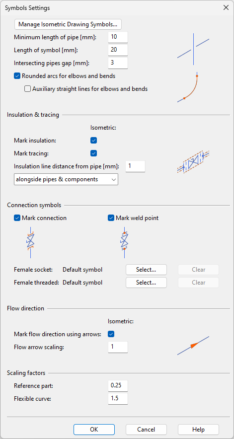
Manage Isometric Drawing Symbols opens an object browser dialog that allows you to browse the symbol library.
Symbol settings
These settings define how to draw symbols that represent piping parts in drawings.
-
Minimum length of pipe [mm] – Define the minimum part length that can be represented in drawings.
-
Length of symbol [mm] – Define the length of symbols. For some symbols this will only be a reference length. See also Height/Length Ratio in Isometric symbol editor.
-
Intersecting pipes gap [mm] – Define the size of the gap to add to the lower line when the lines of two pipes intersect in a drawing (0–6).
-
Rounded arcs for elbows and bends – Select this option to represent elbows and bends using a curved line instead of a sharp corner.
-
Auxiliary straight lines for elbows and bends – Select this option to display an auxiliary line next to elbows and bends.
-
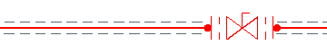
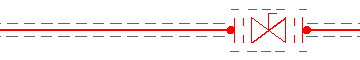
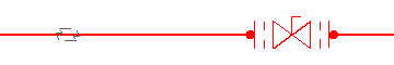
Mark insulation – Select this option to allow insulated pipes to be marked in drawings. Insulation can be marked in three ways:
-
alongside pipes only – Adds the default insulation marking to the sides of pipes, at the specified distance.
-
alongside pipes & components – Adds the default insulation marking to the sides of pipes and piping components.
-
use defined symbol for pipes – Adds the default insulation symbol, or a symbol selected from the symbol library, to the middle of straight pipes.
-
-
Mark tracing – Select this option to allow pipes that use tracing to be marked in drawings.
-
Insulation line distance from pipe [mm] – Define the distance between a pipe and insulation markings along the pipe (1–3 mm).
-
Mark connection – Select this option to mark connections to components with a symbol. You can select separate symbols for female socket and female threaded connections.
-
Female socket – Select a symbol from the symbol library.
-
Female threaded – Select a symbol from the symbol library.
Note: After changing a connection symbol, you must restart the application for the change to take effect.
-
-
Mark weld point – Select this option to mark weld points with a symbol.
-
Mark flow direction using arrows – Select this option to allow pipes to display flow direction arrows. The direction can be changed in the drawing manually, if needed.
-
Flow arrow scaling – Specify a scaling factor for flow direction arrows (0.5–5).
-
Reference part – Specify a scaling factor for reference pipe parts (0.1–1).
-
Flexible curve – Specify a scaling factor for flexible curve parts (0.1–5).